Product Center
Product Center
Location:Home - Products
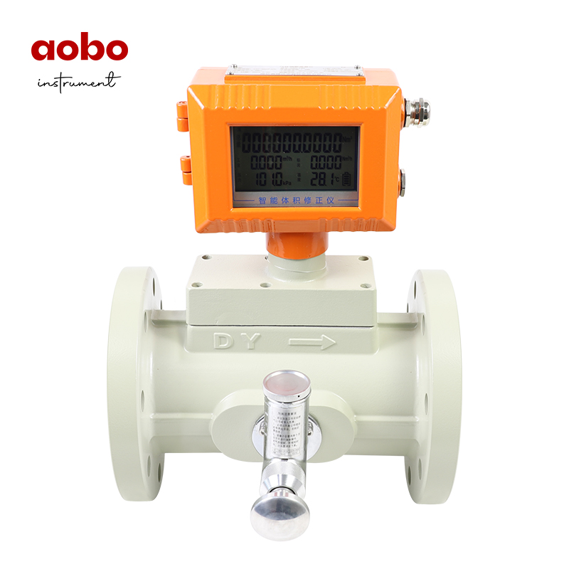
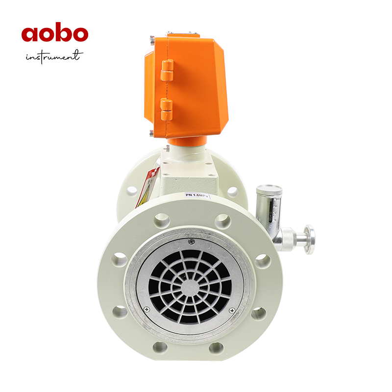
Gas Turbine Flowmeter
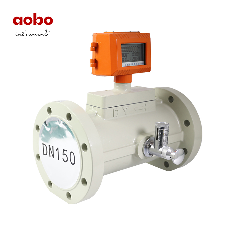
LWQ series gas turbine flowmeter is a new generation of high-precision and high-reliability gas precision measuring instrument, which is based on the advanced technology of flow meters at home and abroad and has been optimized and designed. It integrates the theories of gas mechanics, fluid mechanics, electromagnetism, etc. and integrates temperature, pressure, flow sensors and intelligent flow totalizer. It has excellent low-pressure and high-pressure metering performance, various signal output modes and low sensitivity to fluid disturbance, and is widely suitable for metering natural gas, coal-based gas, liquefied gas and other gases.
Product Details
Product Features
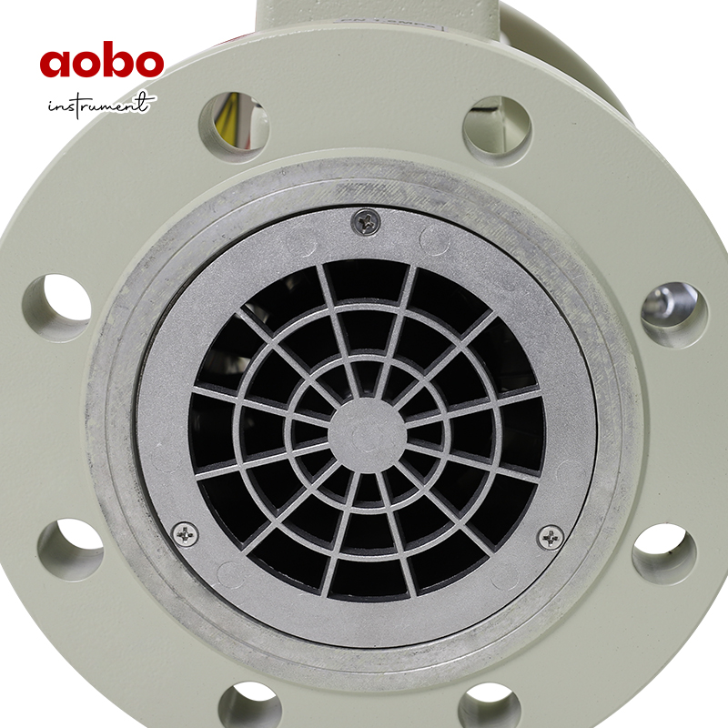
1.High quality alloy turbine with higher flow stability and corrosion resistance;
2.Imported high-quality special bearings with long service life;
3.The metering room is isolated from the ventilation room, thus ensuring the safety of the instrument;
4.It can detect the temperature, pressure and flow rate of the measured gas, automatically track and compensate the flow rate, and display the gas volume accumulation under the standard state (Pb= 101.325 KPa, Tb=293. 15 K); The temperature and pressure values can be queried in real time;
5.Wide flow range (Qmax /Qmin ≥20:1), good repeatability, high accuracy (up to grade 1.0), small pressure loss, low initial flow, up to 0.6 m³/h;
6.Multi-point nonlinear correction of intelligent instrument coefficient;
7.Built-in pressure and temperature sensor, with high safety performance, compact structure and beautiful appearance;
8.The instrument has explosion-proof and protection functions. The explosion-proof marks are ExdⅡBT6 and Exia ⅡCT6, and the protection grade is IP65;
9.The system operates with low power consumption, and a 3.6 V10AH lithium battery can be continuously used for more than one year;
10.Instrument coefficient and cumulative flow value will not be lost after power failure for ten years.
Technical indicators
1.Measuring range

2.Accuracy grade: 1.0 and 1.5
Conditions of use:
1.Ambient temperature: -20℃~+60℃;
2.Atmospheric pressure: 86KPa~106KPa;
3.Medium temperature: -20℃~+80℃;
4.Relative humidity: 5%~95%.
3.Electrical performance index:

4.Model table:

5.Outline Dimensions
The appearance of the flowmeter is shown in Figure 1, and the specific dimensions are shown in.

Note:shows the appearance of temperature and pressure compensation instrument.
The sensor parts of all types of instruments with the same caliber and the height dimensions of the whole machine are consistent.

Selection of Flowmeter
1. When selecting the type, the user should reasonably select the type and specification of the flowmeter according to the nominal pressure of the pipeline, the highest pressure of the medium, the temperature of the medium, the composition of the medium, the flow range and the signal output requirements.
2. In order to optimize the service performance of the flowmeter, the flowrate range of the flowmeter should be within (20%~80%) Qmax.
3. The signal output mode of flowmeter when leaving the factory: working condition pulse signal output (three-wire system), standard flow signal (IC card) output or RS-485 communication output. If other output functions are required, please explain them when ordering.
4. Examples of type selection
It is known that the actual working pressure of a certain gas supply pipeline is (gauge pressure) 0.8 MPa~ 1.2 MPa, the medium temperature range is -5 ℃ ~ +40 ℃ , and the gas supply volume is 3000~8000Nm3/h (standard flow rate). Without considering the natural gas composition, it is required to determine the specification and model of the flowmeter.
Analysis: The flow range given in Table 1 of the instruction is the working condition flow range, while the flow range given in this example is the standard condition flow range. Therefore, the standard condition flow must be converted into the working condition flow according to the gaseous equation before selecting the appropriate caliber.

The data in Table b are for reference only. The data are calculated according to the true relative density of natural gas Gr=0.600 and the molar fractions of nitrogen and carbon dioxide are both 0.00. When the medium pressure is lower than 0.5MPa, they can be estimated according to Zb/Zg= 1. 00.
Calculation: ① When the medium pressure is the lowest (0.8MPa) and the temperature is the highest (+40℃) (in the peak period of gas supply), it shall have the maximum standard volume flow rate (FZ can be temporarily ignored when selecting the type, and the local atmospheric pressure is 101.325 kPa):

Selection: From the above estimation results, it is known that the flow range of the flowmeter to be selected is (213.5~965.472) m3/h. According to Table 1, the flowmeter model to be selected is LWQ- 150.
The value of conversion coefficient C* calculated according to the gaseous equation

Note:
1. The values in the table are calculated based on the local atmospheric pressure of 101.325KPa;
2. Pressure is gauge pressure;