
Product Center
Product Center
Location:Home - Products

Paperless Recorder
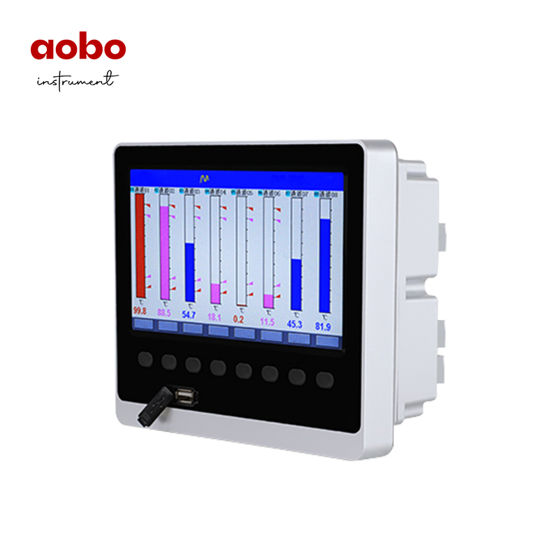
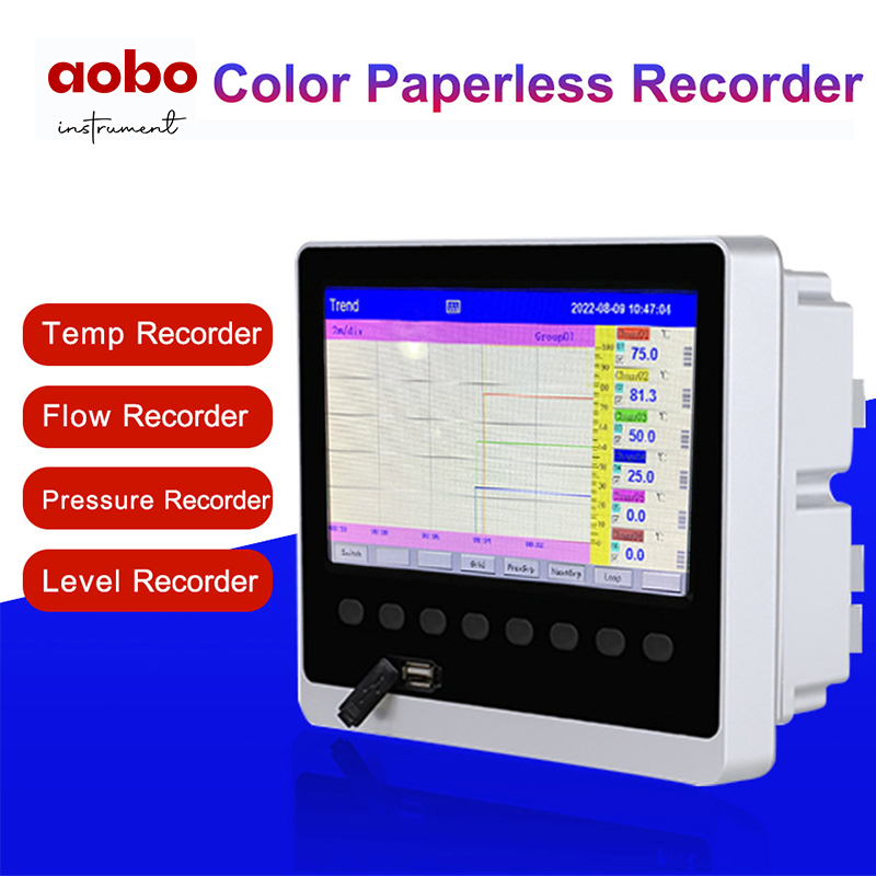
Color paperless recorder has 12-channel universal input (configurable selective input: standard voltage, standard current, thermocouple, thermal resistance, millivolt, etc.). It can be equipped with 12-channel alarming output or 6-channel transmitted output of analog quantity, RS485 communication interface, Ethernet interface, micro printer interface and USB interface, SD card socket; It can provide power distribution for sensor; It has powerful display function, real-time curve display, historical curve recall, and bar chart display, alarming list display, etc. The characteristics of humanized appearance design, perfect function, reliable hardware quality and exquisite manufacturing technology render the instrument a higher performance-price ratio.
Product Details
Overview
Color paperless recorder has 12-channel universal input (configurable selective input: standard voltage, standard current, thermocouple, thermal resistance, millivolt, etc.). It can be equipped with 12-channel alarming output or 6-channel transmitted output of analog quantity, RS485 communication interface, Ethernet interface, micro printer interface and USB interface, SD card socket; It can provide power distribution for sensor; It has powerful display function, real-time curve display, historical curve recall, and bar chart display, alarming list display, etc. The characteristics of humanized appearance design, perfect function, reliable hardware quality and exquisite manufacturing technology render the instrument a higher performance-price ratio.
Technical parameters
Measurement inputs | |
Input signals | Current: 0~20mA, 0~10mA, 4~20mA, 0~10mA radication, 4~20mA radication Voltage: 0~5V, 1~5V, 0~5V radication, 1~5V radication, 0~100mV,±20mV, ±100mV Thermal resistance: Pt100, Cu50, Cu53, Cu100, BA1, BA2 Linear resistance: 0~400Ω Thermal resistance: B, S, K, E, T, J, R, N, F2, Wre3-25, Wre5-26 |
Output | |
Output signals | Analog output: 4~20mA (Load resistance≤380Ω), 0~20mA (Load resistance≤380Ω), 0~10mA (Load resistance≤760Ω), 1~5V (Load resistance≥250KΩ), 0~5V (Load resistance≥250KΩ), 0~10V (Load resistance≥10KΩ) |
Alarming output: Relay normally open contact output, the contact’s capacity 1A/250VAC (resistive load). (! Note: when the load exceeds the contact’s capacity of the relay, please do not carry with load directly) | |
Feed output: DC24V±10%, Load current≤200mA | |
Communication output: RS485/RS232 communication interface, baud rate of 1200-57600 bps can be set, using the standard MODBUS RTU communication protocol, RS485 communication distance can reach 1km; RS232 communication distance can reach 15m; The EtherNet communication interface, the communication rate is 10M. | |
Comprehensive parameters | |
Accuracy of measurement | 0.2%FS±1d |
Display refresh cycle | 1 second |
Setting mode | The panel touch button is set; The parameter’s setting value is locked in password; The setting value is cut off for permanent storage. |
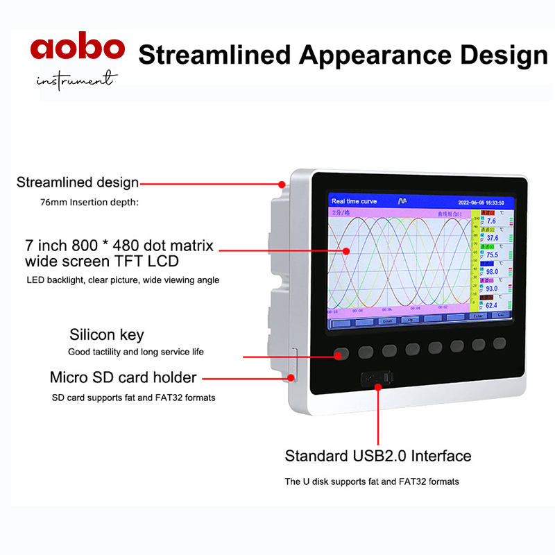
Display mode | With 7 inch 800*480 dot matrix wide screen and TFT high brightness color graphics LCD display, LED backlight, clear screen, wide viewing angle. The display content can be composed of Chinese characters, numbers, process curves, bar charts, etc. Through panel keys, the screen can be paged up and down, the search of historical data before and after, the change of curve time scale, etc. |
Data backup | Support Flash and SD card for data backup and transfer, with the maximum capacity of 8GB, supporting FAT, FAT32 format. |
Memory capacity | The memory capacity of internal Flash: 64M Byte |
Recording interval | 1, 2, 4, 6, 15, 30, 60, 120, 240 seconds ,totally 9 gears, are available for selection. |
Memory length (UPS Continuous recording) | 24 days (while the interval is 1 second)—5825 days (while the interval is 240 seconds) Formula: Recording duration(day)= (! Note: Calculation of the number of channels: The program divides the number of channels into 5 gears ,that is, 4, 8, 16. When the number of instrumentation channels falls between the two gears, the larger number is used as the number of channels. For example, the number of instrument channels is 12-channel, and the number of channels is calculated with 16 in the formula. |
Operating environment | Ambient temperature:-10~50℃ Relative humidity:10 ~ 90%RH (RH); avoid strong corrosive gases. (! Note: In case the site is in bad condition, special instructions must be made when ordering. |
Working power supply | AC85 to 264V (switching power supply), 50/60Hz |
Power Consumption | ≤15W |
Precautions for use of this instrument
●There are more plastic parts for this instrument. When you clean it, please use a dry soft cloth to wipe it. Benzene and banana water etc. should not be used for cleaning, which it may lead to discoloration or deformation.
●Please do not make the live parts approach the signal terminal, which may cause fault.
●Please do not impact this instrument.
●If you confirm that smoke, undesirable odor, abnormal noise and other abnormal situations occur from the instrument, please cut off the power supply immediately and contact the supplier or our company in time.
●In order to ensure the normal work of instrument measurement, please energize the thermal machine for 30 minutes prior to using the instrument.
Precautions for using external storage media
●Storage media is a sophisticated product. Please use it carefully.
●In addition to inserting and removing storage media, please close the operation cover when running. Storage media and USB interface should reduce contact with dust for protection.
●Pay attention to electrostatic protection when using Flash and SD card.
●Recommend the use of our products.
●When using storage media at high temperature (about above 40℃), please insert the storage media when saving the data. After the data is saved, remove it and keep it. Do not keep inserting it into the instrument for a long time.
●Before you switch on or switch off the power, please remove the storage media.
●For general precautions for use of storage media, please refer to the instructions carried for use of the storage media.
Functions and operation of the instrument
The color paperless recorder has multiple operation display screens and configuration screens with the clear display, large amount of information and convenient configuration. Users can operate the instrument conveniently without professional training. After the instrument is connected to the power supply, the initial screen of the system is displayed, the initialization system is completed, and thus the real-time curve screen is entered. The following will introduce each operation display screen and each configuration screen respectively.
Switching of running screens
The running screens consist of real-time curve screen, bar chart screen, digital display screen, historical curve screen, alarming list, file list, printing screen, backup screen, and power-off recording screen and configuration parameters.

Status display

①: Display the name of each running screen.
②: File record mark
Display available: It indicates the file is circularly recording.
Display available with arrow mark: It indicates the file is not circular recording.
Display not available: It indicates the file stops recording.
③: SD card mark
Display available: It indicates SD card is connected.
Display not available: It indicates no SD card is connected.
④: Flash mark
Display available: It indicates flash is connected with instrument.
Display not available: It indicates no flash is connected with instrument.
⑤:Circular display mark
Display available: It indicates circular display for each group.
Display not available: It indicates the fixed screen, no circular display.
⑥: Display the date and time of the operation of the instrument.
Real-time curve screen
According to the combination of curves, the real-time curves and data of 6-channel are displayed simultaneously (the accuracy of the curves is 0.5%±1 character).

①:Time scale: The duration of time expressed in each grid, and the time scale is related to the recording interval. Refer to the table below:
Recording interval | 1S | 2 S | 4 S | 6 S | 15 S | 30 S | 1min | 2 min | 4 min |
Time scale | 2min/grid |
4min/grid | 8min/grid | 12min/grid | 30min/grid | 1h/grid | 2h/grid | 4h/grid | 8h/grid |
4min/grid | 8min/grid | 16min/grid | 24min/grid | 1h/grid | 2h/grid | 4h/grid | 8h/grid | 16h/grid | |
8min/grid | 16min/grid | 32min/grid | 48min/grid | 2h/grid | 4h/grid | 8h/grid | 16h/grid | 32h/grid | |
16min/grid | 32min/grid | 64min/grid | 96min/grid | 4h/grid | 8h/grid | 16h/grid | 32h/grid | 64h/grid |
②: Data curve: Maximum 6 curves can be displayed on the same screen simultaneously(there are 6 kinds of curve colors, which can be set by display configuration).
③: Grid: Convenient for users to estimate time and data value.
④: The time represented by the current grid.
⑤: Curve combination: Display the name of the current curve combination (each curve combination can include six curves, users can put related channels in a curve combination according to their own needs, so as to facilitate data comparison between channel groups.)
⑥:Ruler: The ruler that displays the percentage of curves.
⑦: The name of the channel .It can be set, and the background color is the same as that of the corresponding curve. (As for the setup method, please refer to Section 4.12.4.1: Input Method of Channel’s Bit Number).
⑧: Unit: Display the data unit of the channel and set it up. (As for the setup method, please refer to Section "4.12.4.2 Input Method of Channel’s Unit ").
⑨: Over-limit alarming instructions: From top to bottom, each block in turn is the high high limit, high limit, low limit and low low limit of the over-limit alarming signs. Gray indicates no alarming function , green indicates no alarming, red/pink indicates alarming.
⑩: The display / hidden marks of curves: "√" indicates display of curve, if not, hide the curve.
(11): Operation keys:
Press the “Switch” key to switch to other display screens.
Press the “Time scale" key to switch the time scale.
Press the "Preceding group" key to see the curve combinations of the previous group
Press the "Latter group" key to see the curve combination of the latter group.
Press the "Cycle" key to display the cycle icon " ” on the screen, and automatically switch to the next group of curve combinations according to the cycle interval set in the display configuration.