Product Center
Product Center
Location:Home - Products
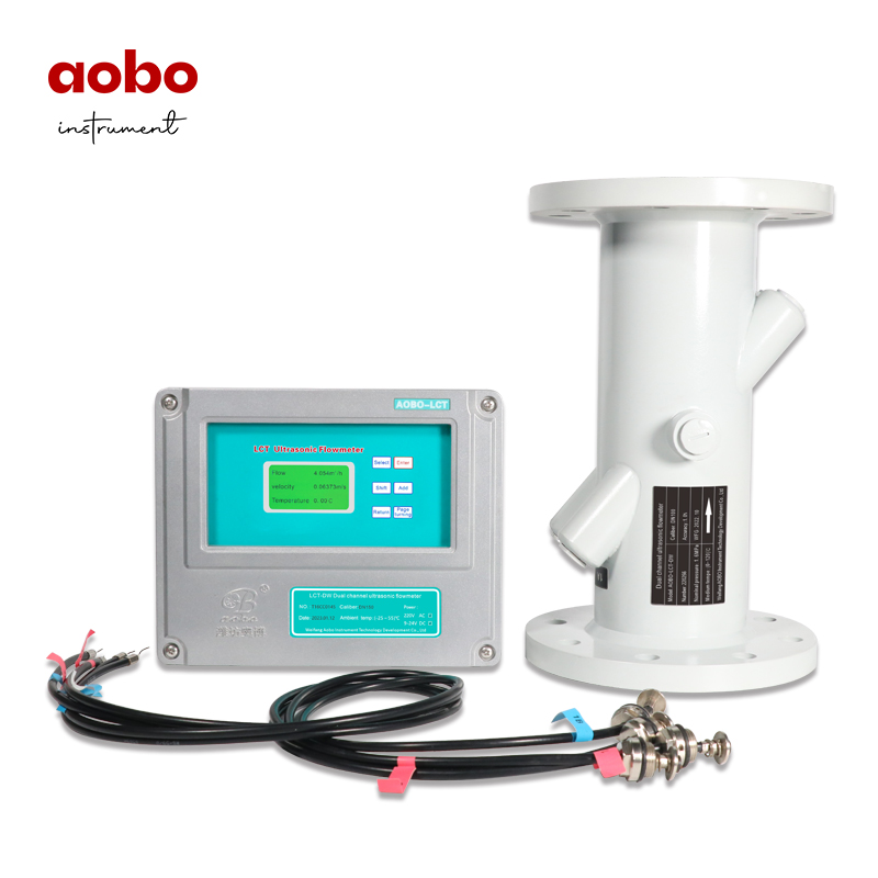
Dual Path Liquid Ultrasonic Flowmeter ABDT-LCT-DW
The LCT Liquid Ultrasonic Flowmeter adopts the time difference method to calculate the flow and uses advanced micro-processing digital technology which is especially suitable for the flow measurement of regional heating,heat source plant ,heat exchange station, HVAC (air conditioning refrigeration equipment) ,tap water and other liquids.
Product Details
Overview
The LCT Liquid Ultrasonic Flowmeter adopts the time difference method to calculate the flow and uses advanced micro-processing digital technology, which is especially suitable for the flow measurement of regional heating, heat source plant, heat exchange station, HVAC (air conditioning refrigeration equipment), tap water and other liquids.
LCT Liquid Ultrasonic Flowmeter includes flow sensor and flow converter; Flow sensor adopts multi-channel ultrasonic wave to measure the medium flow speed of different fluid layers in the pipeline and automatically compensates the cross- section flow speed of the medium in the pipeline. Flow converter adopts a high speed mixed signal processing CPU and it is equipped with high precision time measurement system to achieve 1ps. It has fast dynamic response speed, making higher accuracy of flow speed measurement and repeatability and better stability.
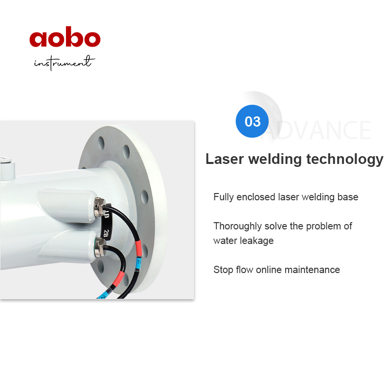
The transducer has the continuous flow maintenance and replacement function to completely solve the sensor leakage problem.
Principle
The LCT ultrasonic flowmeter adopts the measurement principle of time difference method. A sound wave travelling in the direction of flow of the product is propagated at a faster rate than one travelling against the flow, hence the acoustic signal transmission time has a difference (instant difference). The time difference method ultrasonic flowmeter is measured according to the specific principle of the specific relationship between the medium flow speed and the time difference. As long as the time upstream and downstream are accurately determined, the instantaneous flow speed can be found according to the flow speed and its specific relationship and then the instantaneous flow can be caculated.

The transducers (sensors) are installed on both sides of the fluid line and separated by a certain distance. It is assumed that the internal diameter of the pipeline is D and the length of ultrasonic passed is L. The spacing of 2 transducers in the pipeline direction is X and ultrasonic transmission time downstream is t1 and the transmission time upstream is t2. The angle of ultrasonic transmission direction and fluid flow direction is θ, so t1, t2 and can be expressed in the following formula:

Feature
1. No cut-out online maintenance;
2. Strong anti-bubble and anti-interference ability;
3. The sensor resists high temperature and no water leakage;
4. The dynamic response is up to 200 times per second;
5. The turn-down rate is above 1:50;
6. Measure the flow speed of different profiles for the best accuracy;
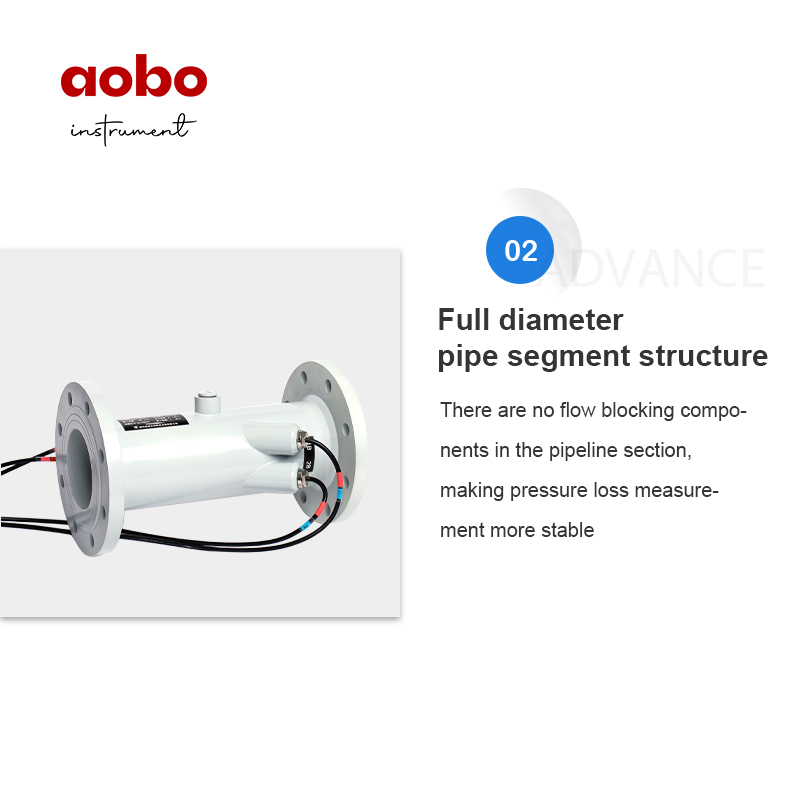
7. Full-pass pipe section structure, with no pressure drop and stable flow speed;
8. Integrated or remote type installation;
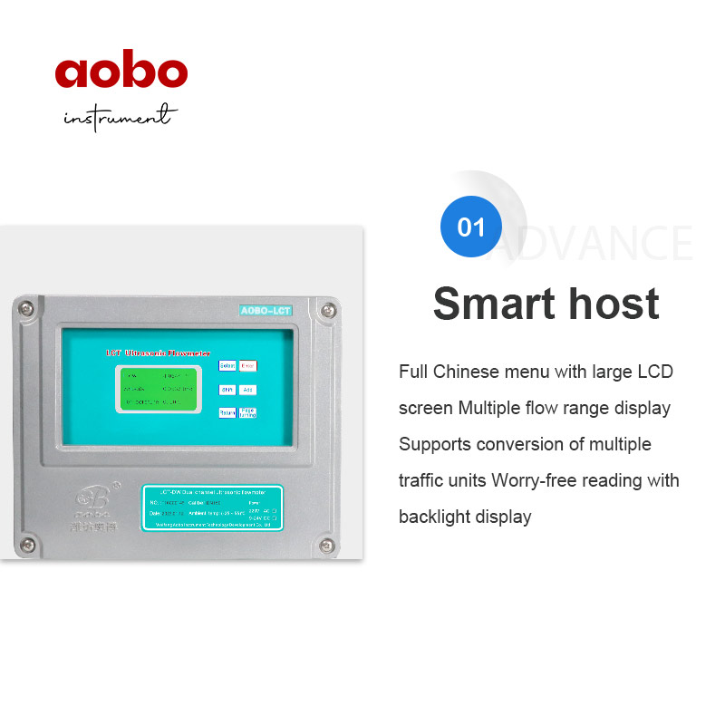
9. 240*128 industrial large screen-LCD display;
10. Measuring liquid is not affected by electrical conductivity;
11. One-way up to 5000Hz high-speed pulse output;
12. One-way standard (4-20) mA current output;
13. M-BUS communication interface;
14. RS232/485 interface, standard MODBUS protocol.
Parameter
Nominal general diameter: DN50-DN2000;
Measurement medium(s): clean single liquid;
Medium temperature: ≤130℃;
Accuracy: 1.0%;
Repeatability: 0.2%;
Turn-down rate: above 1:50
Case material: carbon steel; stainless steel;
Power supply: AC220V±10%, 50Hz or(10-36)VDC;
Signal output: pulse equivalent (0.01-9999) L/N (set), stability of 30ppm, standard current (4-20)mA output;
Communication output: M-BUS communication interface, RS232/485 interface, standard MODBUS protocol.
Flow Converter
The flow converter has a hardware temperature compensation circuit and software temperature compensation model, which is more suitable for heating high-temperature water metering compared to other flow meters to ensure the accuracy of flow measurement at different temperatures. Equipped with 6 multi-function buttons, industrial large screen LCD display, optional Chinese and English menu, humanized design and simple operation.
High-performance measurement chip, instrument instantaneous flow resolution 0.001m³/h, cumulative flow resolution 0.1L.
The instrument can output 1-way of high-speed pulse, range (1-5000)Hz, pulse equivalent(0.01-9999.99)L/N can be set.
The instrument can output a 1-way(4-20)mA signal.
The instrument supports standard current signal input, measure range (4-20)mA, resolution 0.001mA.
Case size
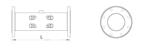
size(mm)

Installation requirements
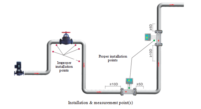
Measurement point selection
The Liquid Ultrasonic Flowmeter is the simplest and most convenient in the installation of all flowmeters. Simply select a suitable measuring point and input the pipe parameters at the measuring point into the flow converter to install the sensor. When selecting the measurement point, the selection of the fluid field is required to ensure the measurement accuracy. The following principles shall be followed during the installation:
When installing clamp-on type ultrasonic flowmeter, select pipe sections with uniform density and easy ultrasonic transmission.
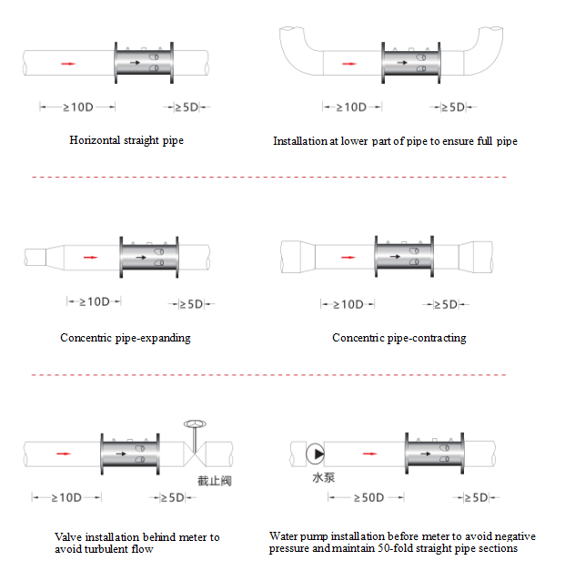
Installation precautions
Keep long enough straight pipe section upstream and downstream of the ultrasonic flow sensor (D is the sensor diameter) as required in the figure below.
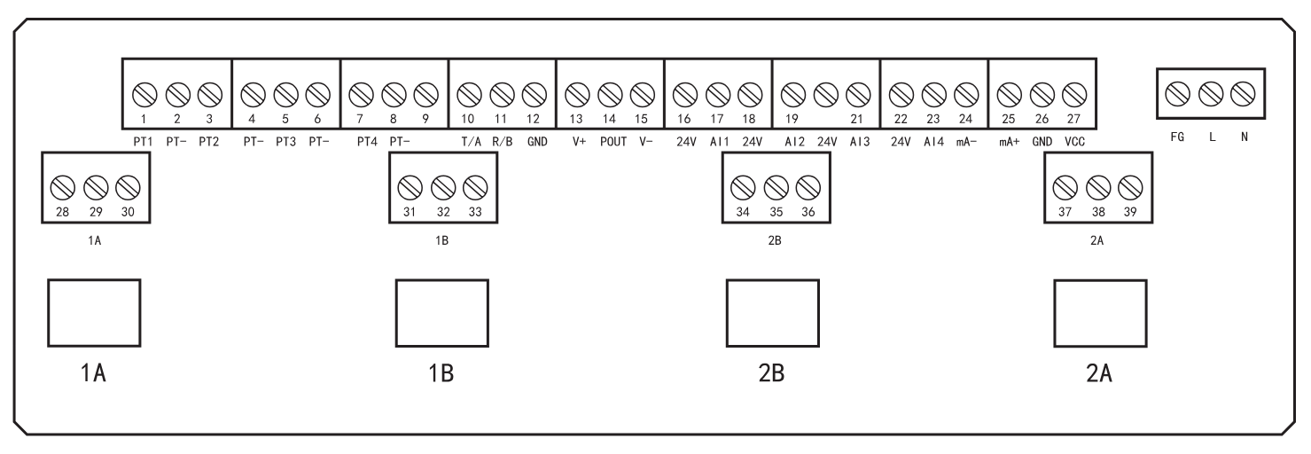
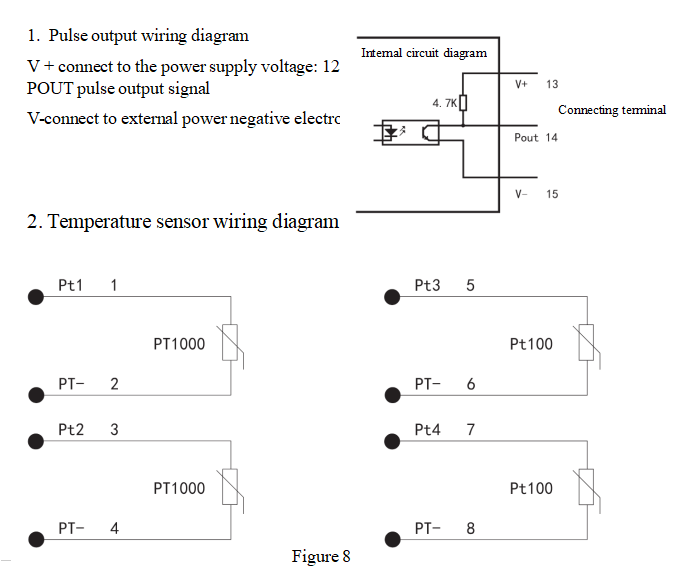
Flowmeter wiring
Once the flowmeter is installed in the specified position as required, the wiring can be started. Open the upper cover of the meter and see the terminal of the converter. For specific wiring, please refer to the figure below:
Production Type Selection

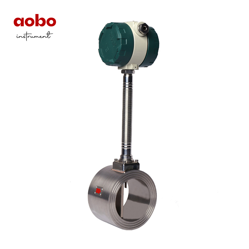
Vortex Flowmeter
Vortex flow meters are mainly used for measuring the flow rate of pipeline medium fluids, such as gases, liquids, steam, and other media. When measuring the volumetric flow rate under operating conditions, they are almost unaffected by parameters such as fluid density, pressure, temperature, and viscosity. The vortex flowmeter adopts a piezoelectric stress sensor with high reliability and long service life, and can operate within the operating temperature range of (-20-350) ℃. There are analog
View Products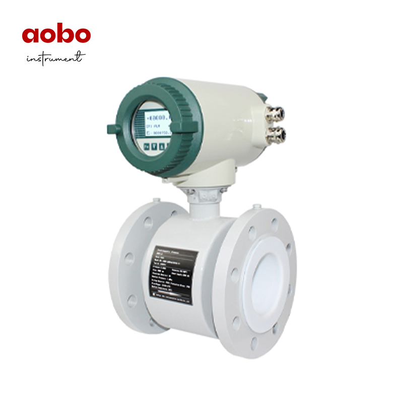
Electromagnetic Flowmeter
The ABDT-LD series intelligent electromagnetic flowmeter is a relatively mature liquid measurement instrument, suitable for measuring the volume flow rate of conductive liquids (conductivity ≥ 5 µ s/cm) and slurries in closed pipelines. It is suitable for various acid, alkali, salt solutions, clean water, seawater, sewage, mud, pulp, mineral pulp, low conductivity liquids, etc. Widely used in industrial production process control, energy metering, environmental protection, sewage treatment an
View Products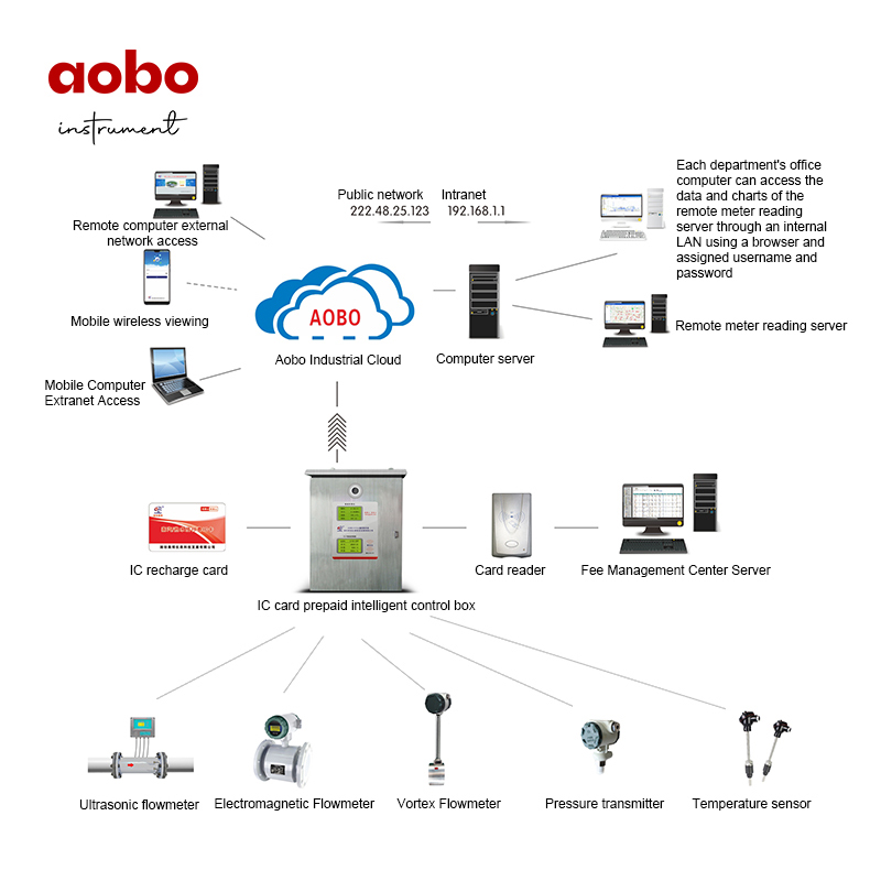
Steam/Hot Water IC Card Prepaid Intelligent Control System
In order to avoid billing disputes between energy supply and demand parties, reduce conflicts, and enable energy consuming units to consume clearly, Weifang Aobo Instrument independently developed and produced an IC card prepayment intelligent measurement and control system in 2008 that integrates early warning, anti-theft, and battery life functions, achieving a "payment before consumption" mode, completely solving the problems of difficult charging, meter reading, and management in thermal pow
View Products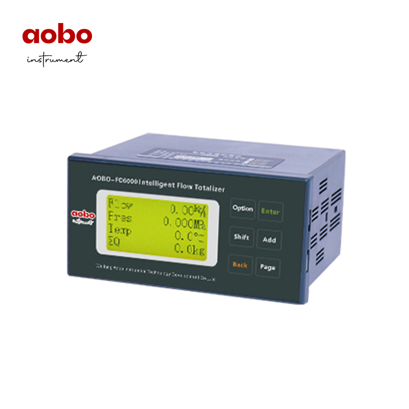
FC6000 intelligent flow totalizer
AOBO-FC6000 intelligent flow totalizer is a universal flow computer with intelligent Chinese and English menu configuration built on a brand new platform. It completes the flow measurement and calculation functions for steam, gas, and liquid with faster calculation speed, lower power consumption, and more reliable working performance. It can compensate for the temperature and pressure of the fluid in real-time online, and can simultaneously receive signals such as flow, temperature, and pressure
View Products