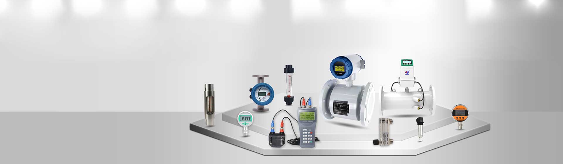
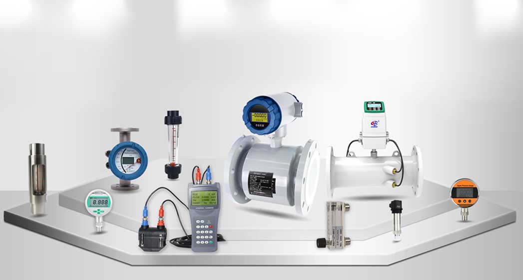
Product Center
Product Center
Location:Home - Products
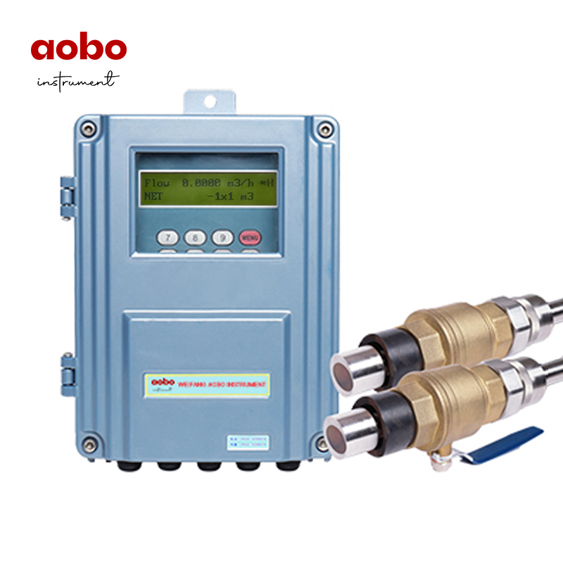
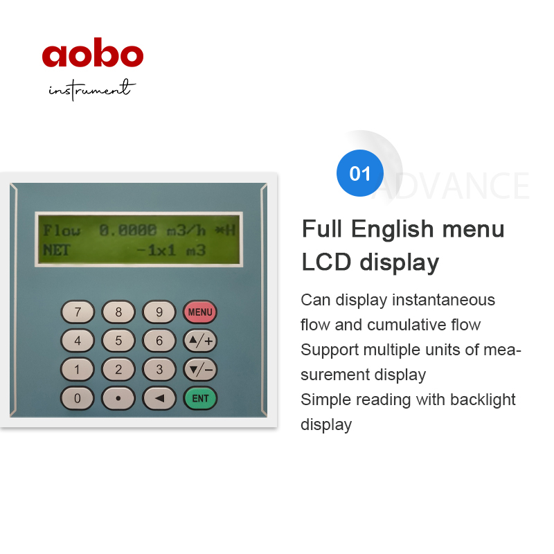
Plug-in Ultrasonic Flowmeter
The ABDT-LCT series ultrasonic flowmeter is a universal time difference ultrasonic liquid flowmeter designed using ultra large scale integrated circuits and low voltage, wide pulse emission technology. It is suitable for continuously measuring the flow rate of homogeneous liquids without high concentration suspended particles or gases in industrial environments.
Product Details
Overview
LCT series ultrasonic flowmeter is a general time difference ultrasonic liquid flowmeter designed by using VLSI and low-voltage wide pulse emission technology. It is suitable for continuous measurement of homogeneous liquid without high concentration suspended particles or gas in industrial environment.
Function Characteristics
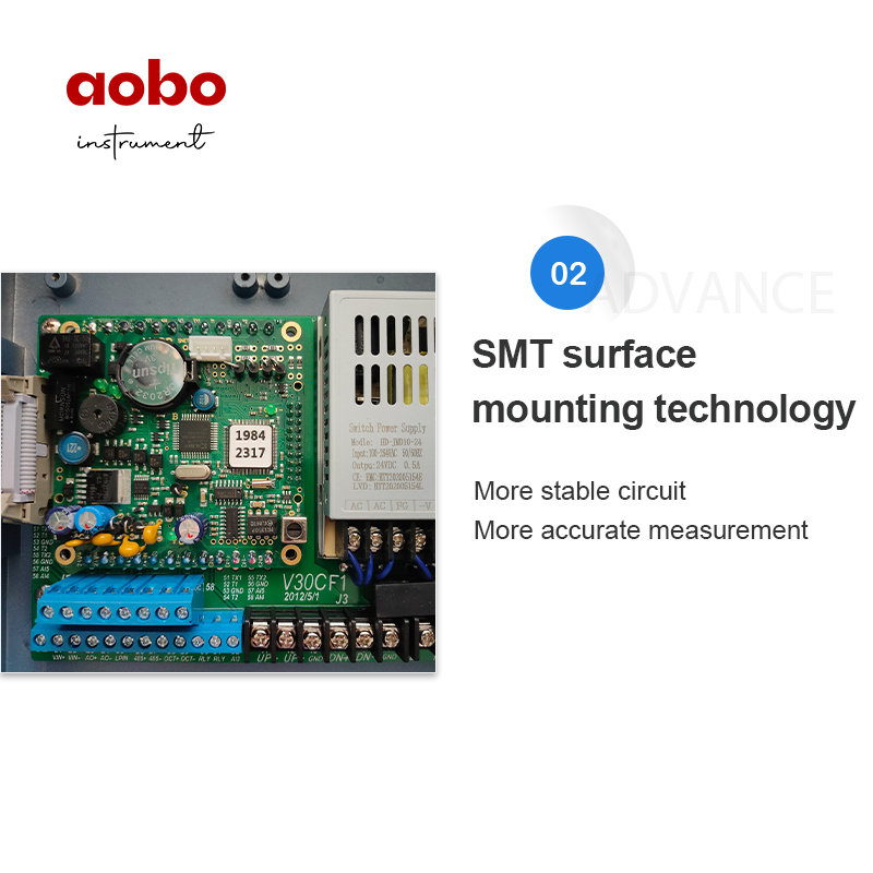
1. Hardware modular design, easy production and maintenance operation;
2. Built in 4M byte data recorder and record 200000 lines of timing output or real-time printing data;
3.Electrical isolation RS485 interface, including more than 10 kinds of communication protocols such as MODBUS, M-BUS and FUJI;
4. Electrical isolation 0~20mA or 4~20mA current loop output, optional loop power supply mode (two-wire system);
5. Optional HART Protocol;
6. Heat measurement function in accordance with CJ128 national heat meter standard;
7. 8~36VDC,220VAC power supply mode is optional;
8. It has the functions of manual accumulator and batch controller;
9. The cumulative recording function of month, year and day; and record the cumulative flow, cumulative heat and other data in the first 512 days (every day) and the first 128 months (every month);
10. Record and review the power-off time and other data of the previous 32 times;
11. The interval can be set from 1 second to 24 hours. There are up to 22 outputs;
12. Three analog inputs with accuracy of 0.1%.
Please know the working power supply and model of the product before use to prevent abnormal operation or damage caused by misconnection.
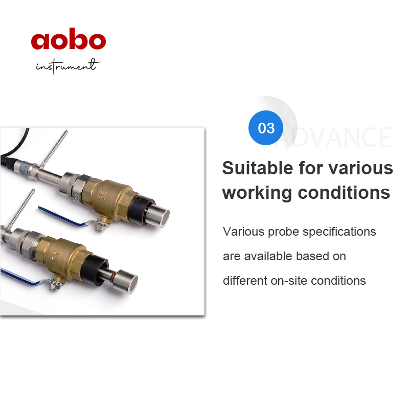
Insertion type transducer installation method
Installation method: Z method, applicable to above DN80
Sensor type: insert type B
Installation tools: special opening tools provided by the company, 400W electric hand drill (preferably adjustable speed), wrench, etc.
Locate the installation point
Input the pipe parameters on the mainframe, the installation space L (L=inside diameter-9.113mm) will be calculated. (the two sensors must be located in the same axis plane), the installing space L should be the distance between the centers of the two sensors horizonally.
A. Making a fixed position paper:take a 4D(D refers to the pipe inner diameter) long and 200mm (or D) wide rectangular paper (according to actual situation on spot, the paper tape can also be replaced by moisture-and-corrosion resistant materials), and draw a line about 100mm from the edge; Wrap the fixed position paper on the cleaned surface of the pipe, making sure that the two paper sides are overlapping and aligned and thus the line drawn may be parallel with the pipe axis.

B. Extend the straight line on the fixed position paper, draw a straight line on the pipe, and the intersection point between the drawn straight line and an edge of the positioning paper is A; Starting from point A, measure 1 / 2 of the circumference of the pipe along the edge of the positioning paper. The parallel intersection is C. draw a straight line parallel to the pipe axis at point C (that is, parallel to the straight line on the positioning paper).

Removing the fixed position paper and starting from C, the installation space L should be measured along the line, draw on the pipe ,the point is B. Thus, A and B are the points where the transducers are to be installed. For example, L=280mm. Then A two bases of ball valves should be welded respectively on A and B, making sure the centers of bases overlap A and B respectively.

Welding the base of the ball valves
For pipes that can be welded (such as steel and stainless steel, etc.), just weld the base on the pipe (Stainless steel pipe should be welded to stainless base,please indicate in your order). Before welding, the rust and paint on the section where the sensors are to be installed shall be cleaned up by using an angle grinder, and the oil dirty and dust should be cleaned by using acetone or alcohol. to prevent water leakage,so the work of welding is very important, making sure the centers of bases overlap A and B respectively,no air bubbles.
For pipes which material cannot be welded directly (such as cast iron and cement, etc.), special hoops (with airproof rubber pads) should be used. The bases of the ball valves have been welded on the hoops.
These hoops are directly fixed on the pipe and make sure that the centers of the ball valves overlap A and B respectively. Finally, the ball valves should be closely fixed on the bases welded on the hoops to prevent water leakage.

Hole-drilling

Length calculation of the part of transducer into the pipe inner wall
Insertion style transducer is made of stainless steel by casting. As the transducer's length A and the pipe wall's thickness B are known,and the length part of transducer left outside the pipe can be measured, the length of the inner part of the transducer can be calculated through the formula: L=A-B, C=0
Note:the length A of different types of transducers are:Standard insertion type B:A=170mm;Standard insertion type C:A=220mm,and Cement insertion type B:A=310mm.

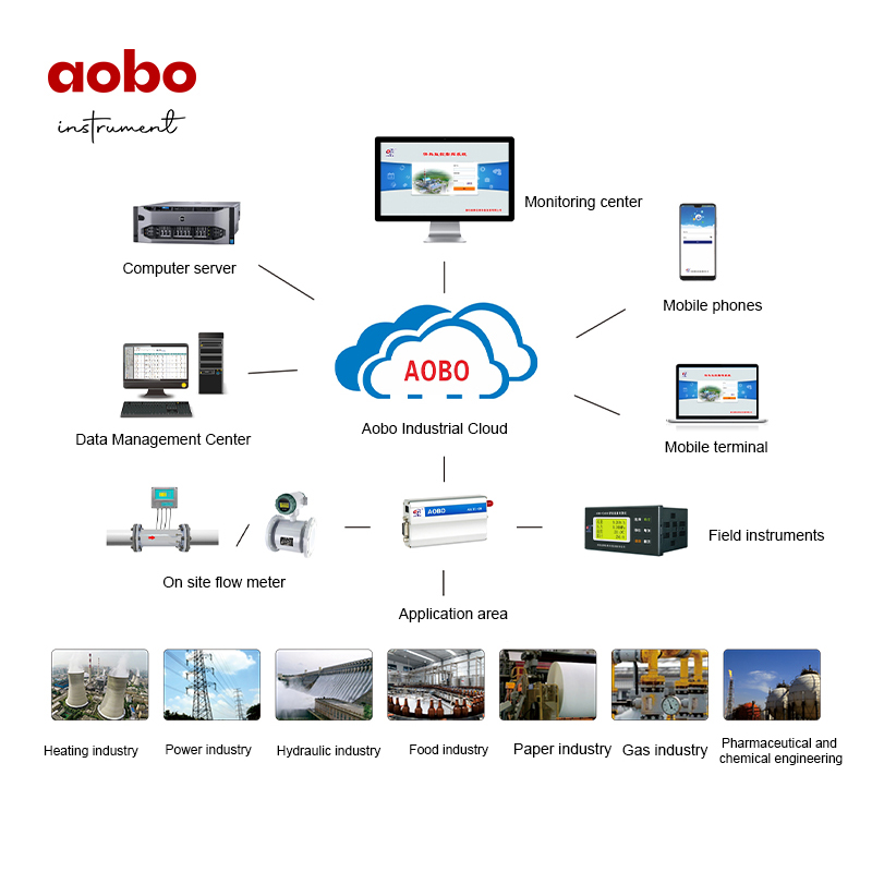
ABDT-RM remote meter reading system
In order to meet the various needs of users for measurement and energy conservation, our company has independently developed an intelligent remote meter reading system (energy management) that adapts to various user needs. In terms of software and hardware, it adopts standardized and reliable design, and meets national standards. Widely used in fields such as thermoelectric, chemical, natural gas, papermaking, pharmaceuticals, biotechnology, urban heating, etc. After several years of practical o
View Products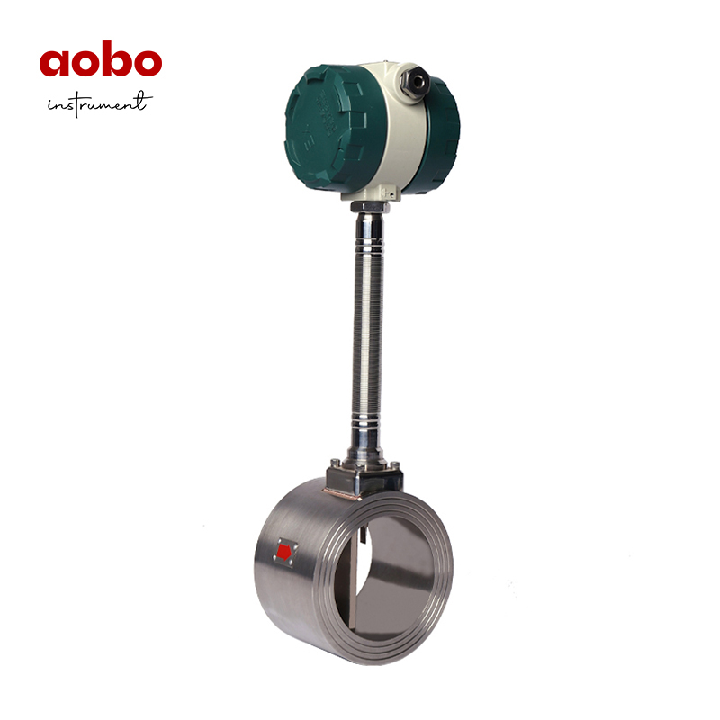
Vortex Flowmeter
Vortex flow meters are mainly used for measuring the flow rate of pipeline medium fluids, such as gases, liquids, steam, and other media. When measuring the volumetric flow rate under operating conditions, they are almost unaffected by parameters such as fluid density, pressure, temperature, and viscosity. The vortex flowmeter adopts a piezoelectric stress sensor with high reliability and long service life, and can operate within the operating temperature range of (-20-350) ℃. There are analog
View Products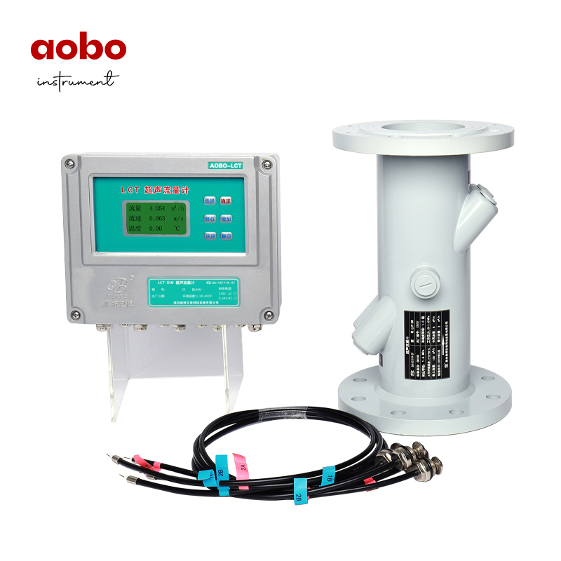
ultrasonic flowmeter
The LCT ultrasonic flow meter uses the time difference method to calculate the flow rate, and utilizes advanced micro processing digital technology. It is particularly suitable for measuring the flow rate of liquids such as regional heating, heat source plants, heat exchange stations, HVAC (air conditioning and refrigeration equipment), and tap water. LCT ultrasonic flow meter includes a flow sensor and a flow converter; The flow sensor adopts multi-channel ultrasound to measure the flow velocit
View Products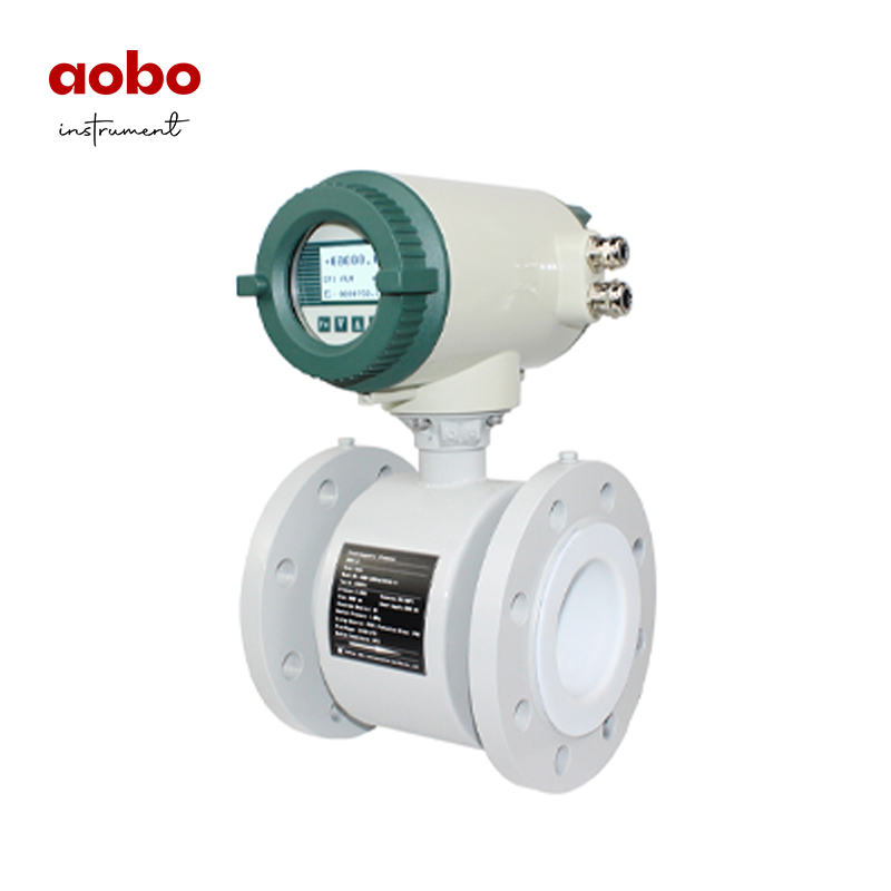
Electromagnetic Flowmeter
The ABDT-LD series intelligent electromagnetic flowmeter is a relatively mature liquid measurement instrument, suitable for measuring the volume flow rate of conductive liquids (conductivity ≥ 5 µ s/cm) and slurries in closed pipelines. It is suitable for various acid, alkali, salt solutions, clean water, seawater, sewage, mud, pulp, mineral pulp, low conductivity liquids, etc. Widely used in industrial production process control, energy metering, environmental protection, sewage treatment an
View Products